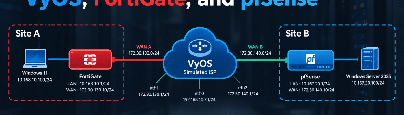

How I turned a Server Core host into a two-site WAN sandbox without leaving VLAN 10.
Introduction
Practicing multi-site networking usually means either renting real circuits or pretending two VMs on the same LAN are “remote sites.” Neither option teaches you how edge firewalls behave when they sit behind an upstream provider, do NAT, and only talk to each other across someone else’s routing domain.
I wanted something closer to production: two independent sites, each with its own WAN subnet and LAN, both reaching the internet through a simulated ISP.
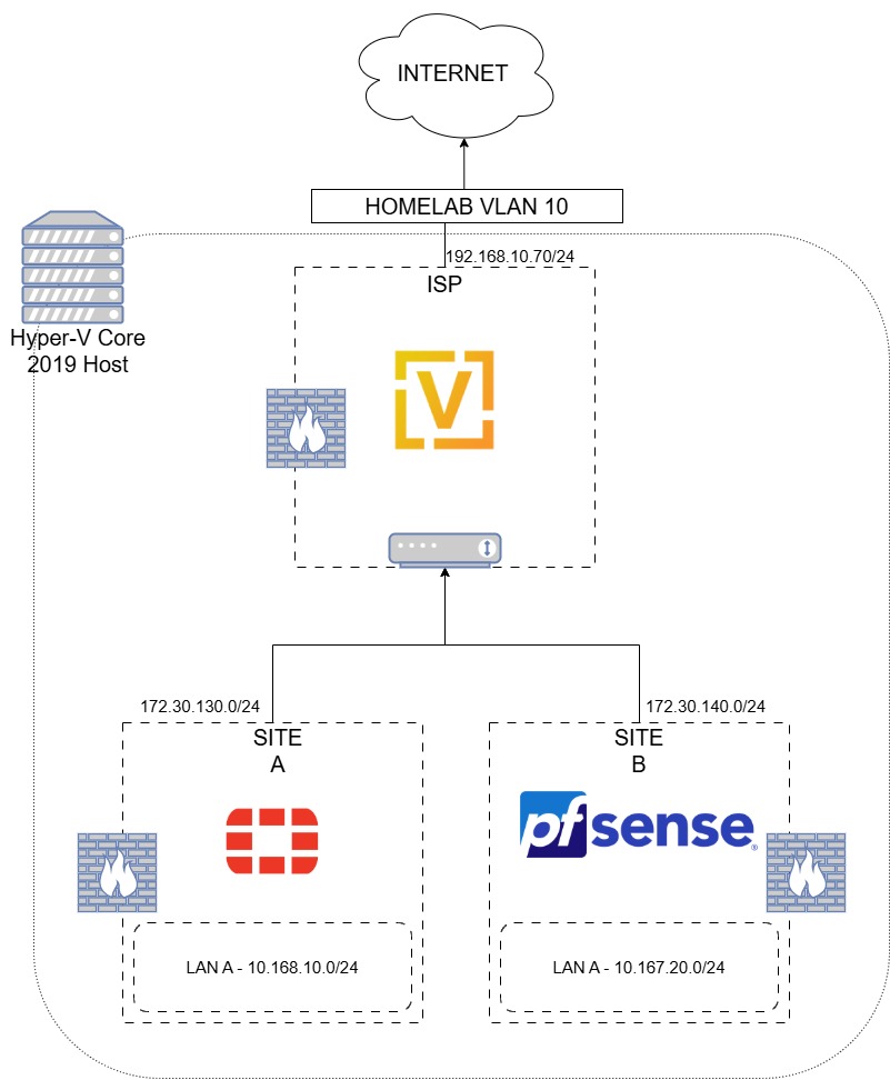
The lab runs on a single Windows Server 2019 Server Core Hyper-V host. That host lives on my real Homelab VLAN 10. To the simulated ISP world, VLAN 10 is the internet edge. Inside Hyper-V, internal switches carve out WAN A, WAN B, LAN A, and LAN B. VyOS plays the ISP. A FortiGate VM is Site A. pfSense is Site B.
This post is Part 1 of the series — a full walkthrough of the Hyper-V switches, VyOS ISP, FortiGate, and pfSense configs that get both sites online. Part 2 will cover site-to-site IPsec between FortiGate and pfSense (including selective service allowlisting and packet captures).
Architecture
The architecture is intentionally simple. One physical host. One real uplink. Everything else is virtual.
Required Components
- Windows Server 2019 Server Core (Hyper-V) – Host, domain-joined. Management NIC on Homelab VLAN 10.
- VyOS 2026.03 (Circinus) – Simulated ISP / upstream router with NAT toward the real homelab (and internet).
- FortiGate Free / evaluation VM – Site A edge firewall (requires a FortiCare account to activate free license).
- pfSense – Site B edge firewall.
- Windows 11 25H2 Evaluation VM – Client on Site A LAN (or any OS you prefer).
- Windows Server Evaluation VM – Client on Site B LAN (or any OS you prefer).
Hyper-V / Physical Network
HV1 has two physical NICs with distinct jobs:
- Ethernet – Management at on Homelab VLAN 10.
- Ethernet 2 – Dedicated VM uplink connected to Homelab VLAN 10; used by the virtual network path toward “real” upstream.
IMPORTANT
The Hyper-V management OS is not attached to the internal lab switches. Keeping the host OS off those switches avoids accidental bridging between management and the simulated WAN/LAN topology.
Target Topology
Implementation
This implementation assumes you already have the following resources available:
- A Hyper-V host on Server 2019 Server Core (or equivalent) with a spare NIC for VM traffic
- ISO/images for VyOS, FortiGate, pfSense, and your client VMs
- Comfort working on Server Core via remote management / PowerShell / Hyper-V Manager from another machine
- A FortiCare account (required to license the FortiGate evaluation image)
- Internal DNS or a public resolver (mine is
192.168.10.210)
Create the Hyper-V Virtual Switches
On the Hyper-V host, create four internal switches — one for each lab segment:
New-VMSwitch ` -Name "WAN Network A" ` -SwitchType InternalNew-VMSwitch ` -Name "WAN Network B" ` -SwitchType InternalNew-VMSwitch ` -Name "LAN Network A" ` -SwitchType InternalNew-VMSwitch ` -Name "LAN Network B" ` -SwitchType Internal
Long story short: if the host OS is a member of WAN Network A or LAN Network A, you will spend an afternoon debugging “why is my lab leaking into management” instead of learning firewalls. Keep the management OS off these internal switches.
Provision and Identify VyOS NICs
We’ll configure VyOS first. Provision the VyOS VM with three NICs mapped like this:
- eth0 → VM Network / Homelab VLAN (real upstream)
- eth1 → WAN Network A
- eth2 → WAN Network B
Boot VyOS and identify the attached NICs:
show interfacesip addressip -br link
Confirm eth0 is your upstream / Homelab VLAN adapter before continuing.
Configure VyOS Upstream (eth0)
Assuming eth0 is the WAN / upstream toward Homelab VLAN 10, run:
configureset interfaces ethernet eth0 address '192.168.10.70/24'set protocols static route 0.0.0.0/0 next-hop 192.168.10.1set system name-server 192.168.10.210set system host-name 'vyos-isp'commitsaveexit
Replace 192.168.10.1 with whatever your real edge router is on that VLAN, and swap 192.168.10.210 for your internal DNS or a public resolver such as 1.1.1.1.
Then confirm basic reachability:
ping 192.168.10.1ping 1.1.1.1ping google.com
If VyOS cannot get out eth0, neither site will, no amount of FortiGate or pfSense tuning will fix a broken ISP.
Enable SSH Management on VyOS
Enable SSH on the upstream so you can manage VyOS from your Homelab VLAN (the “WAN” from the simulated ISP’s point of view):
configureset service ssh port '22'commitsaveexit
From a machine on your real LAN / VLAN, manage VyOS with:
ssh vyos@192.168.10.70
Configure WAN Network A on VyOS (eth1)
Next, bring up the Site A WAN subnet:
configureset interfaces ethernet eth1 address '172.30.130.1/24'commitrun show interfacessaveexit
Deploy FortiGate on WAN A
At this point, set up the FortiGate on WAN Network A. Obtain an NVA / permanent free trial image from Fortinet and license it via the CLI. You will need a FortiCare account.
Useful references:
Attach the FortiGate WAN NIC to WAN Network A before continuing.
Add Masquerade NAT for WAN A
Before the FortiGate can reach the real world, VyOS needs to take traffic from 172.30.130.0/24, translate it to 192.168.10.70, and send it through the real Homelab VLAN 10 gateway. That is the normal masquerade / SNAT model in VyOS:
configureset nat source rule 100 outbound-interface name 'eth0'set nat source rule 100 source address '172.30.130.0/24'set nat source rule 100 translation address 'masquerade'commitsaveexit
Configure FortiGate WAN (port1)
On the FortiGate, identify interfaces:
get system interfaces
For me the WAN was port1. Configure a static address on WAN A:
config system interfaceedit port1set mode staticset ip 172.30.130.10 255.255.255.0set allowaccess ping https sshnextend
Then configure the FortiGate default route toward VyOS:
config router staticedit 1set dst 0.0.0.0 0.0.0.0set gateway 172.30.130.1set device port1nextend
Validate the route:
get router info routing-table all
You should see something like:
S* 0.0.0.0/0 [10/0] via 172.30.130.1, port1
Lastly, test reachability to the WAN gateway (VyOS), then internet:
execute ping 172.30.130.1execute ping 192.168.10.1execute ping 1.1.1.1execute ping google.com
If all of those work, the FortiGate has internet access through the simulated ISP!
Configure WAN Network B on VyOS (eth2) + NAT
Now set up the Site B WAN side on the ISP before bringing up pfSense:
configureset interfaces ethernet eth2 address '172.30.140.1/24'set nat source rule 101 outbound-interface name 'eth0'set nat source rule 101 source address '172.30.140.0/24'set nat source rule 101 translation address 'masquerade'commitsaveexit
Validate:
show interfaces
You should now have the following on VyOS:
eth0 192.168.10.70/24eth1 172.30.130.1/24eth2 172.30.140.1/24
Configure pfSense WAN on WAN Network B
pfSense is more GUI-driven. Install from the ISO, attach the WAN NIC for WAN Network B, and configure the WAN interface with:
IP: 172.30.140.10Mask: 255.255.255.0Gateway: 172.30.140.1DNS: 192.168.10.210
IMPORTANT
Make sure you enable VLAN tagging on the WAN interface in pfSense if your Homelab / DNS path requires it, especially if you are using internal DNS. I hit a weird quirk here while imaging / bringing up the pfSense NVA on WAN B, and missing VLAN tagging caused the process to fail.
At this point the WAN side of the architecture looks like this:
                         Internet
                            |
                     192.168.10.1
                            |
                     192.168.10.70
                         VyOS
                   "Simulated ISP"
                    /           \
                   /             \
        172.30.130.0/24       172.30.140.0/24
             WAN A                 WAN B
Configure FortiGate LAN A (port2) + DHCP
Now move on to the LANs with Site A first. On the FortiGate, attach port2 to LAN Network A and configure it:
config system interface edit "port2" set mode static set ip 10.168.10.1 255.255.255.0 set allowaccess ping https ssh set alias "LAN-A" nextend
Verify:
show system interface port2
Then configure DHCP on LAN A:
config system dhcp server edit 1 set interface "port2" set default-gateway 10.168.10.1 set netmask 255.255.255.0 set dns-server1 192.168.10.210 config ip-range edit 1 set start-ip 10.168.10.100 set end-ip 10.168.10.115 next end nextend
Confirm:
show system dhcp serverget system interface physical
IMPORTANT: FortiGate DHCP VCI Matching
I hit a weird issue here: the DHCP server was set to respond only to clients whose DHCP Vendor Class Identifier (VCI) matched FortiSwitch or FortiExtender. I presume that came from a FortiLink-style port configuration I had touched by mistake. A plain Windows 11 VM does not advertise those VCIs, so it sat lease-less while everything “looked configured.”
Remove the restriction:
config system dhcp server edit 1 set vci-match disable nextend
Boot your LAN A client VM (I used Windows 11 25H2 Eval — use whatever you like and get creative). Confirm it receives a lease in 10.168.10.100–10.168.10.115, uses gateway 10.168.10.1, and can reach the internet through FortiGate > VyOS > Homelab.
Configure pfSense LAN B (hn1) + DHCP
On Site B, add NIC2 (hn1) for LAN Network B and configure it in the pfSense UI:
IPv4 Address: 10.167.20.1Subnet Mask: 255.255.255.0Default Gateway: NONEDNS: 192.168.10.210
IMPORTANT: LAN Gateway Must Be NONE
Then set up DHCP on this interface for 10.167.20.100–10.167.20.115. Use automatic outbound NAT and the standard LAN allow rule.
When I first did this, I mistakenly set the LAN default gateway to 10.167.20.1. After booting the Windows Server client onto LAN B, I couldn’t reach anything and had no internet. In the firewall logs I saw the client denied by the default allow LAN-to-any rule, and traffic that looked like 0.0.0.0:68 blocked outbound toward 255.255.255.255:67 (DHCP).
It turned out hn1 (LAN) had an upstream gateway set, which made pfSense treat it like a WAN / routed interface. Setting the LAN gateway to NONE fixed it.
I run OPNsense at home and in production, but I’m newer to pfSense. Despite them being nearly identical, I missed this on the first pass. Please note it when configuring LAN B.
Correct Site B path once fixed:
Windows Server10.167.20.x | vpfSense10.167.20.1 | v172.30.140.10 | vVyOS172.30.140.1 | vHomelab / Internet
End-to-End Smoke Tests
On each client VM:
ipconfig/Get-NetIPConfiguration— correct lease, gateway, DNS- Ping the local firewall LAN IP
- Ping VyOS on that site’s WAN gateway (
172.30.130.1or172.30.140.1) - Resolve and reach a known internet host
When both sites pass those checks independently, Part 1 is done. You now have a fake ISP and two “branches” that do not yet trust each other over IPsec.
Troubleshooting – Tips
FortiGate DHCP and VCI Matching
If Windows gets no lease but FortiGate DHCP “looks fine,” check for VCI matching left over from FortiSwitch / FortiExtender / FortiLink-style config:
config system dhcp server edit 1 set vci-match disable nextend
pfSense LAN Gateway Trap
Correct configuration:
- WAN hn0 –
172.30.140.10/24, gateway172.30.140.1 - LAN hn1 –
10.167.20.1/24, gateway NONE
If LAN has an upstream gateway pointed at itself (or anything else), pfSense will treat that interface like a WAN and your client internet path will fall apart.
pfSense WAN VLAN Tagging
If imaging / bringing up pfSense on WAN B fails when using internal DNS, double-check VLAN tagging on the WAN interface. That quirk bit me once and is easy to overlook.
Quick Isolation Checklist
If a site has no internet:
- Does the client have a DHCP lease and correct gateway?
- Can the client reach the firewall LAN IP?
- Does the firewall WAN have a gateway (VyOS)?
- Can the firewall ping VyOS on its WAN?
- Can VyOS reach Homelab / internet on eth0?
- Is masquerade present for that WAN subnet (rule 100 / 101)?
Work from the client toward the ISP. Do not start packet-capturing IPsec until both sites are boringly online.
Conclusion
At this point the lab is complete for Part 1. With Hyper-V internal switches, VyOS as a simulated ISP, FortiGate on WAN A, and pfSense on WAN B, both sites have their own LAN, their own WAN subnet, and independent internet access through NAT on VyOS — without leaving Homelab VLAN 10.
In Part 2 of this lab we’ll set up the IPsec tunnels and pass traffic for specific services only like SFTP, tight allowlisting, and packet captures to prove what is (and isn’t) crossing the tunnel.
Additional Notes & References:
- VyOS documentation (interfaces / NAT): https://docs.vyos.io/
- FortiGate-VM evaluation license (Hyper-V): https://docs.fortinet.com/document/fortigate-private-cloud/8.0.0/microsoft-hyper-v-administration-guide/504166/fortigate-vm-evaluation-license
- FortiGate administration guide: https://docs.fortinet.com/document/fortigate/8.0.1/administration-guide/441460
- pfSense interface and gateway documentation: https://docs.netgate.com/pfsense/
- Hyper-V virtual switches overview: https://learn.microsoft.com/en-us/windows-server/virtualization/hyper-v/deploy/configure-virtual-networking
If you’d like help designing multi-site topologies, edge firewall labs, or production VPN architectures, feel free to reach out to Algo IT Pro LLC for consulting and implementation services.

 Kohanik Secure